${ formatSectionTitle(diameter) } (${ productsByDiameter(diameter).length } Results)
No products found. Please adjust your search criteria.
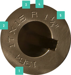
Reading Your ACME Prop
Finding and knowing your ACME propeller’s unique prop number — as well as the technical information that’s found on each ACME prop — makes the process of replacements easier.
- Part Number
- Diameter x Pitch
- Constant/Variable (Sport)
- Left/Right Rotation
- Bore/Shaft Diameter